| Vai al negozio / Goto Shop =>> | |||||||
Sistema Digitale DVB-T
Digital DVB-T System
Basics of DVB-T
Rather than carrying one data carrier on a single radio frequency (RF) channel, COFDM works by splitting the digital data stream into a large number of slower digital streams, each of which digitally modulate a set of closely spaced adjacent sub-carrier frequencies. In the case of DVB-T, there are two choices for the number of carriers known as 2K-mode or 8K-mode. These are actually 1,705 or 6,817 sub-carriers that are approximately 4 kHz or 1 kHz apart.
DVB-T offers three different modulation schemes (QPSK, 16QAM, 64QAM).
DVB-T has been adopted or proposed for digital television broadcasting by many countries (see map), using mainly VHF 7 MHz and UHF 8 MHz channels whereas Taiwan, Colombia, Panama, Trinidad and Tobago and the Philippines use 6 MHz channels. Examples include the UK's Freeview.
The DVB-T Standard is published as EN 300 744, Framing structure, channel coding and modulation for digital terrestrial television. This is available from the ETSI website, as is ETSI TS 101 154, Specification for the use of Video and Audio Coding in Broadcasting Applications based on the MPEG-2 Transport Stream, which gives details of the DVB use of source coding methods for MPEG-2 and, more recently, H.264/MPEG-4 AVC as well as audio encoding systems. Many countries that have adopted DVB-T have published standards for their implementation. These include the D-book in the UK, the Italian DGTVi, the ETSI E-Book and Scandivia NorDig.
DVB-T has been further developed into newer standards such as DVB-H (Handheld), which was a commercial failure and is no longer in operation, and DVB-T2, which was initially finalised in August 2011.
DVB-T as a digital transmission delivers data in a series of discrete blocks at the symbol rate. DVB-T is a COFDM transmission technique which includes the use of a Guard Interval. It allows the receiver to cope with strong multipath situations. Within a geographical area, DVB-T also allows single-frequency network (SFN) operation, where two or more transmitters carrying the same data operate on the same frequency. In such cases the signals from each transmitter in the SFN needs to be accurately time-aligned, which is done by sync information in the stream and timing at each transmitter referenced to GPS.
The length of the Guard Interval can be chosen. It is a trade off between data rate and SFN capability. The longer the guard interval the larger is the potential SFN area without creating intersymbol interference (ISI). It is possible to operate SFNs which do not fulfill the guard interval condition if the self-interference is properly planned and monitored.
Technical description of a DVB-T transmitter
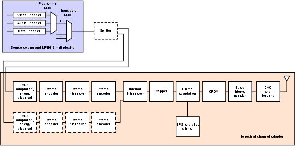
With reference to the figure, a short description of the signal processing blocks follows.
- Source coding and MPEG-2 multiplexing (MUX)
- compressed video, compressed audio, and data streams are multiplexed into MPEG program streams (MPEG-PSs). One or more MPEG-PSs are joined together into an MPEG transport stream (MPEG-TS); this is the basic digital stream which is being transmitted and received by TV sets or home Set Top Boxes (STB). Allowed bitrates for the transported data depend on a number of coding and modulation parameters: it can range from about 5 to about 32 Mbit/s (see the bottom figure for a complete listing).
- Splitter
- two different MPEG-TSs can be transmitted at the same time, using a technique called Hierarchical Transmission. It may be used to transmit, for example a standard definition SDTV signal and a high definition HDTV signal on the same carrier. Generally, the SDTV signal is more robust than the HDTV one. At the receiver, depending on the quality of the received signal, the STB may be able to decode the HDTV stream or, if signal strength lacks, it can switch to the SDTV one (in this way, all receivers that are in proximity of the transmission site can lock the HDTV signal, whereas all the other ones, even the farthest, may still be able to receive and decode an SDTV signal).
- MUX adaptation and energy dispersal
- the MPEG-TS is identified as a sequence of data packets, of fixed length (188 bytes). With a technique called energy dispersal, the byte sequence is decorrelated.
- External encoder
- a first level of error correction is applied to the transmitted data, using a non-binary block code, a Reed-Solomon RS (204, 188) code, allowing the correction of up to a maximum of 8 wrong bytes for each 188-byte packet.
- External interleaver
- convolutional interleaving is used to rearrange the transmitted data sequence, in such a way that it becomes more rugged to long sequences of errors.
- Internal encoder
- a second level of error correction is given by a punctured convolutional code, which is often denoted in STBs menus as FEC (Forward error correction). There are five valid coding rates: 1/2, 2/3, 3/4, 5/6, and 7/8.
- Internal interleaver
- data sequence is rearranged again, aiming to reduce the influence of burst errors. This time, a block interleaving technique is adopted, with a pseudo-random assignment scheme (this is really done by two separate interleaving processes, one operating on bits and another one operating on groups of bits).
- Mapper
- the digital bit sequence is mapped into a base band modulated sequence of complex symbols. There are three valid modulation schemes: QPSK, 16-QAM, 64-QAM.
- Frame adaptation
- the complex symbols are grouped in blocks of constant length (1512, 3024, or 6048 symbols per block). A frame is generated, 68 blocks long, and a superframe is built by 4 frames.
- Pilot and TPS signals
- in order to simplify the reception of the signal being transmitted on the terrestrial radio channel, additional signals are inserted in each block. Pilot signals are used during the synchronization and equalization phase, while TPS signals (Transmission Parameters Signalling) send the parameters of the transmitted signal and to unequivocally identify the transmission cell. The receiver must be able to synchronize, equalize, and decode the signal to gain access to the information held by the TPS pilots. Thus, the receiver must know this information beforehand, and the TPS data is only used in special cases, such as changes in the parameters, resynchronizations, etc.
- OFDM Modulation
- the sequence of blocks is modulated according to the OFDM technique, using 1705 or 6817 carriers (2k or 8k mode, respectively). Increasing the number of carriers does not modify the payload bit rate, which remains constant.
- Guard interval insertion
- to decrease receiver complexity, every OFDM block is extended, copying in front of it its own end (cyclic prefix). The width of such guard interval can be 1/32, 1/16, 1/8, or 1/4 that of the original block length. Cyclic prefix is required to operate single frequency networks, where there may exist an ineliminable interference coming from several sites transmitting the same program on the same carrier frequency.
- DAC and front-end
-
the digital signal
is transformed into
an analogue signal,
with a
digital-to-analogue
converter (DAC),
and then modulated
to radio frequency (VHF,
UHF) by the RF
front-end. The
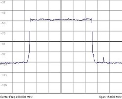
occupied bandwidth
is designed to
accommodate each
single DVB-T signal
into 5, 6, 7, or 8
MHz wide
channels. The base
band sample rate
provided at the DAC
input depends on the
channel bandwidth:
it is
 samples/s,
where
 is the channel
bandwidth expressed
in Hz.
| Available bitrates (Mbit/s) for a DVB-T system in 8 MHz channels | |||||
|---|---|---|---|---|---|
| Modulation | Coding rate | Guard interval | |||
| 1/4 | 1/8 | 1/16 | 1/32 | ||
| QPSK | 1/2 | 4.976 | 5.529 | 5.855 | 6.032 |
| 2/3 | 6.635 | 7.373 | 7.806 | 8.043 | |
| 3/4 | 7.465 | 8.294 | 8.782 | 9.048 | |
| 5/6 | 8.294 | 9.216 | 9.758 | 10.053 | |
| 7/8 | 8.709 | 9.676 | 10.246 | 10.556 | |
| 16-QAM | 1/2 | 9.953 | 11.059 | 11.709 | 12.064 |
| 2/3 | 13.271 | 14.745 | 15.612 | 16.086 | |
| 3/4 | 14.929 | 16.588 | 17.564 | 18.096 | |
| 5/6 | 16.588 | 18.431 | 19.516 | 20.107 | |
| 7/8 | 17.418 | 19.353 | 20.491 | 21.112 | |
| 64-QAM | 1/2 | 14.929 | 16.588 | 17.564 | 18.096 |
| 2/3 | 19.906 | 22.118 | 23.419 | 24.128 | |
| 3/4 | 22.394 | 24.882 | 26.346 | 27.144 | |
| 5/6 | 24.882 | 27.647 | 29.273 | 30.160 | |
| 7/8 | 26.126 | 29.029 | 30.737 | 31.668 | |
Technical description of the receiver
The receiving STB adopts techniques which are dual to those ones used in the transmission.
- Front-end and ADC: the analogue RF signal is converted to base-band and transformed into a digital signal, using an analogue-to-digital converter (ADC).
- Time and frequency synchronization: the digital base band signal is searched to identify the beginning of frames and blocks. Any problems with the frequency of the components of the signal are corrected, too. The property that the guard interval at the end of the symbol is placed also at the beginning is exploited to find the beginning of a new OFDM symbol. On the other hand, continual pilots (whose value and position is determined in the standard and thus known by the receiver) determine the frequency offset suffered by the signal. This frequency offset might have been caused by Doppler effect, inaccuracies in either the transmitter or receiver clock, and so on. Generally, synchronization is done in two steps, either before or after the FFT, in such way to resolve both coarse and fine frequency/timing errors. Pre-FFT steps involve the use of sliding correlation on the received time signal, whereas Post-FFT steps use correlation between the frequency signal and the pilot carriers sequence.
- Guard interval disposal: the cyclic prefix is removed.
- OFDM demodulation: this is achieved with an FFT.
- Frequency equalization: the pilot signals are used to estimate the Channel Transfer Function (CTF) every three subcarriers. The CTF is derived in the remaining subcarriers via interpolation. The CTF is then used to equalize the received data in each subcarrier, generally using a Zero-Forcing method (multiplication by CTF inverse). The CTF is also used to weigh the reliability of the demapped data when they are provided to the Viterbi decoder.
- Demapping: since there are Gray-encoded QAM constellations, demapping is done in a "soft" way using nonlinear laws that demap each bit in the received symbol to a more or less reliable fuzzy value between -1 and +1.
- Internal deinterleaving
-
Internal decoding: uses the Viterbi algorithm, with a traceback length larger than that generally used for the basic 1/2 rate code, due to the presence of punctured ("erased") bits.
- External deinterleaving
- External decoding
- MUX adaptation
- MPEG-2 demultiplexing and source decoding
Countries and territories using DVB-T

America
Europe
|
OceaniaAsia |

